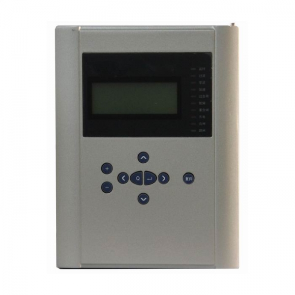
Line Protective Relay Device
The BEPR-811U Digital Line Protection is a packaged line protection basically configured of current, voltage and 3-phas e reclosing relays. It is applicable for the line and Busbar at the voltage levels of 66kV or less.
The protection device adopts perfect software synchronous sampling technology, control on both sides of the sample synchronization error less than 4 degrees, improve the differential protection action precision.
Two fundamental CPU modules are provided. One of them is a relay constructed of the 32-bit microprocessors. This unit is fitted with the large volume RAM and Flash Memory, and is powerful enough to carry out data processing, logic calculation and information storage. Another CPU is a general man-machine interface constructed of a single-chip computer. Two CPUs are independent to each other. All protection and automation functions are implemented by software. The logic relations in protection comply with the principle of “four unification ”
Product Features and Benefits:
- All English character LCD display, and clear and easy man-machine interface.
- The precision of the selected measuring modules (including KWH metering ) can reach to the class 0.5.
- To provide access to the accumulated pulse-degree side.
- High speed Ethernet interface is provided to integrated the IEC 870-5-103 standard communication protocol.
- High precision clock chips are used. The GPS time checking circuit is provided to realize the clock synchronism of the whole system.
- High speed Ethernet interface is provided to integrated the IEC 870-5-103 standard communication protocol.
- The core of CPU, the protection functional module is the powerful 32-bit micro- processors with large capacity RAM and Flash Memory. They are powerful to process data, perform logic calculation and store information. 8 to 50 recorded reports and 1000 events can be recorded. These information will not be lost even in power interruption.
Complete protection function configuration
Table 1 Types and functional configuration of this series products
| Function | BEPR- 811U | ||||
| Phase current differential | |||||
| P-p directional current zones II, III | √ | ||||
| Zero-sequence directional current zone II, III | √ | ||||
| Current inverse time-limit | √ | ||||
| Zero-sequence inverse time-limit | √ | ||||
| Directional blocking | √ | ||||
| Voltage blocking | √ | ||||
|
3-phase reclosing |
Synchronism or no voltage | √ | |||
| Asynchronism | √ | ||||
| 2nd shot reclosing | √ | ||||
| acceleration | Pre-acceleration | √ | |||
| Post-acceleration | √ | ||||
|
Manual closing acceleration |
√ | ||||
| LF, LV load shedding | √ | ||||
| Overload | √ | ||||
| Telecontrol function pressure plate | √ | ||||
| Telemeter | Measurement TA | alternative use | |||
| Protection TA | alternative use | ||||
| Telesignal | alternative use | ||||
| Telecontrol | alternative use | ||||
| KWH | KWH measurement | √ | |||
| GPS time-checking | √ | ||||
| False blocking prevention | √ | ||||
| Remote management | √ | ||||
Monitoring
Telemeter:Ia, Ib, Ic, Ua, Ub, Uc, P, Q, f and other analog telemetry
Telecontrol:Division and the normal remote control circuit breaker
Telesignal:16way telesignalling open into the volume of the collection, installation of remote signal deformation, events, letters and other remote
Remote pulse: 2-way electric-degree pulse input
Out: Device has a 13 way out, of which 10 road trip because of the export-driven relay, 3-way signal drive for the notice of police.
GPS time-checking
Technical Parameters
Rated parameters
Rated D.C. voltage : 220V or 110V ( as required )
Rated A. C. data
a) Phase voltage 100 / V
b)Tapped voltage of the line: 100V or 100 /V
c) A.C current 5A or 1A( as required )
d) Rated frequency 50 Hz
Power consumption :
a) D.C circuit normal : not larger than 25W
operation: not larger than 40W
b) A.C voltage circuit not larger than 0.5VA for each phase
c) A.C current circuit not larger than 1VA for each phase (for 5A rating )
not larger than 0.5VA for each phase ( for 1A rating )
Status voltage :
Input voltage to CPU and signal interface 24V (18V~ 30V )
Input voltage to GPS time checking 24V (18V ~ 30V )
Output status (optic coupled output ) permissive voltage 24V ( 18V ~ 30V )
Driving power 150 mA
Main technical performance
Operating range for sampling circuits (10% tolerance )
voltage : 0.4V ~120V
current : 0.08In ~ 20In
Contact capacity
current capacity of the signal circuit contact 400VA
arc-breaking capacity of the signal circuit contact 60VA
Tripping and closing current
CB tripping current 0.5A, 1A, 1.5A, 2A, 2.5A, 3A, 3.5A, 4A ( as required )
CB closing current 0.5A, 1A, 1.5A, 2A, 2.5A, 3A, 3.5A, 4A ( as required )
Precision of elements
current elements <± 5%
voltage element <± 5%
synchronism-check angle: <± 1°
timing element <± 20 ms
frequency deviation: <±0.02Hz
slip rated value: <± 5%
Operating Time of the complete protection ( including time needed by relay )
Fixed operating time of the instantaneous zone when measured at 1.2 times of setting value: not longer than 40 ms
Precision of measuring circuits for analog variables monitoring device equipped with the special measurement sub-module :
current, voltage : class 0.2
power, KWH : class 0.5
Insulation property
Insulation resistance
Insulating resistance between active parts and passive parts or casings and electrically unrelated circuits is measured by the 500 megaohmmeter to be not less than 50MΩ for the various circuits at different levels under the normal test atmospheric conditions.
Strength of insulating media
Under the normal test atmospheric conditions, the protection can withstand the power frequency withstand voltage test of 50 Hz, 2000V and 1 min. without any breakdown flashover and element damages. During the test, as a voltage is applied at any tested circuit, the other circuits are inter connected and grounded with an equivalent potential.
Impact voltage
Under the normal test atmospheric conditions, the short-duration impact voltage test of 1.2 /50 µs standard lightning wave is done on the power input circuits. AC input circuits, output contact circuit to the ground and between circuits. The open test voltage is 5 kV.
Heat and moisture-proof performance
The protection can withstand the heat and moisture-proof test stipulated in the Chapter 20, GB/T 7261. The alternating heat and moisture-proof test is to be done at the highest temperature +40ºC, the maximum humidity 95%, for 48 hrs and at a cycle of 24 hrs. In 2 hrs before the test is finished, according to the requirements in section 2.3.1, the insulation resistance between the conducting circuits and external passive metals and casings and electrically unrelated parts are measured to be not less than 1.5 MΩ, the withstand voltage strength of the media not less than 75% of the voltage magnitude of the media strength test stipulated in the section 2.3.2
Electromagnetic compatibility properties
Electrostatic discharge anti-interference
The protection conforms to the standard GB/T17626.2-1998, electrostatic discharge anti-interference test class 4
RF electromagnetic field radiation anti-interference
The protection conforms to the standard GB/T17626.3-1998, RF electromagnetic field radiation anti-interference test class 3
Electric fast transient pulse group anti-interference
The protection conforms to the standard GB/T17626.4-1998, electric fast transient pulse group anti-interference test class 4
Surge(impulse) anti-interference
The protection conforms to the standard GB/T17626.5-1998, surge (impulse) anti-interference test class3
RF field induced conduction interference
The protection conforms to the standard GB/T17626.6-1998, RF field induced conduction interference test class 3
Power frequency magnetic field anti-interference
The protection conforms to the standard GB/T17626.8-1998, Power frequency magnetic field anti-interference test class 5
Pulse magnetic field anti-interference
The protection conforms to the standard GB/T 17616.9-1998, Pulse magnetic field anti-interference test class 5
Damp oscillation magnetic field anti-interference
The protection conforms to the standard GB/T 17626.10, damp oscillation magnetic field anti-interference test class 5
Oscillation wave anti-interference
The protection conforms to the standard GB/T 17626.12-1998, Oscillation wave anti-interference test class 4
Radiated emission value limiting test
The protection conforms to the standard GB9254-1998, radiated emission value limiting test class A
Mechanical performance
Vibration
The protection can withstand the impact duration test of the severity class I stipulated in the section 16.2of GB 7261.
Impact
The protection can withstand the impact duration test of the severity class I stipulated in the section 17.4 of GB 7261.
Crash
The protection can withstand the impact duration test of the severity class I stipulated in the Chapter 18 of GB 7261.
Environment conditions
Ambient temperature :
operation : -20ºC~ +55ºC , less than 35ºC after 24 hours operation
storage : -25ºC ~ +70ºC , no exciting variables are applied at the limit value and no irreversible changes occur. The protection will operate normally after the recovery of temperature.
Relative humidity : maximum monthly average humidity 90 % at the lowest temperature of 25ºC, (no condensation ). At the highest temperature of +40ºC, maximum humidity must not be over 50 %.
Atmospheric pressure : 86 ~ 106 kPa ( relative altitude above sea level is less than 2 km ).
Hardware
High reliability is fully considered both in the overall design and module design. It is reliable in program implementation signal indication and communication. Therefore in the panel-assembling operations or the installation of the protection into the switchboard, no additional AC and DC input anti-interference modules are required.
Application
It is applicable for the line and Busbar at the voltage levels of 66kV or less.