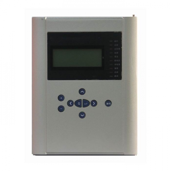
Transformer Protective Relay for 66KV Substation and Less
The BEPR-833U Series Digital Station Transformer Protection is a packaged station transformer protection basically configured of current, voltage and non-electric quantity relays. It is applicable for substation or power plant transformers at the voltage levels of 66KV or less.
Two fundamental CPU modules are provided. One of them is a relay constructed of the 32-bit microprocessors. This unit is fitted with the large volume RAM and Flash Memory, and is powerful enough to carry out data processing, logic calculation and information storage. Another CPU is a general man-machine interface constructed of a single-chip computer . Two CPUs are independent to each other. All protection and automation functions are implemented by software.
Complete protection function configuration
| Function | BEPR-833U | |
| inter-phase faults | √ | |
| Overload | √ | |
| Current acceleration protection | √ | |
| The zero-sequence current relay | √ | |
| Low-voltage protection | √ | |
| Non-electric quantity protection | √ | |
| Telemeter | Measurement TA | √ |
| Protection TA | √ | |
| Telesignal | √ | |
| Telecontrol | √ | |
| KWH | Pulse measurement | √ |
| GPS time-checking | √ | |
| False blocking prevention | √ | |
| Remote management | √ | |
- 2-zone phase to phase current relay that reacts to inter-phase faults.
- Overload alarm and tripping functions.
- Acceleration zone that can be individually set and react to the automatic switching-in onto the permanent faults.
- Zero-sequence current relay that can react to the single-phase ground faults in a directly grounded system.
- The zero-sequence current relay can operate both in the definite time limit or inverse time limit mode.
- Loss of voltage relay blocked by current and TV wire break.
- Auto-detection on TV wire break.
- Non-electric quantity protection for transformer.
Integrated design
- Telemeter, tele-control and tele-signal functions
- The precision of the selected measuring modules (including KWH metering ) can reach to the class 0.5.
- For users having special KWH meters, accumulated pulse KWH connectors are provided.
- False blocking-preventive measures and signal indications for this partition.
- The device has its own operation circuit to trip or close circuit breakers and it is not necessary to in-stall the other equipments.
- Real moisture-proof, dust-proof, and shock-proof design, suitable to be installed in site, e.g., switchboard.
Monitoring
- Telemeter:Ia, Ib, Ic, Ua, Ub, Uc, P, Q, f and other analog telemetry.
- Telecontrol:Division and the normal remote control circuit breaker.
- Telesignal:16way telesignalling open into the volume of the collection, installation of remote signal deformation, events, letters and other remote.
- Remote pulse: 2-way electric-degree pulse input.
- Out: Device has a 13 way out, of which 10 road trip because of the export-driven relay, 3-way signal drive for the notice of police.
- GPS time-checking.
Technical Parameters
Rated parameters
Rated D.C. voltage : 220V or 110V ( as required )
Rated A. C. data
a) Phase voltage 100 / V
b)A.C current 5 A or 1 A (as required )
c) Rated frequency 50 Hz
Power consumption :
a) D.C circuit normal : not larger than 8W
operation: not larger than 12W
b) A.C voltage circuit not larger than 0.5VA for each phase
c) A.C current circuit not larger than 1VA for each phase (for 5A rating )
not larger than 0.5VA for each phase ( for 1A rating )
Status voltage :
Input voltage to CPU and signal interface 24V (18V~ 30V )
Output status (optic coupled output ) permissive voltage 24V ( 18V ~ 30V )
driving power 150 mA
Main technical performance
Operating range for sampling circuits (5% tolerance )
voltage : 0.4V ~120V
current : 0.08In ~ 20In
Zero-sequence current: 20mA ~ 5.00A
Contact capacity
current capacity of the signal circuit contact 400VA
arc-breaking capacity of the signal circuit contact 60VA
Tripping and closing current
CB tripping current 0.5A, 1A, 1.5A, 2A, 2.5A, 3A, 3.5A, 4A ( as required )
CB closing current 0.5A, 1A, 1.5A, 2A, 2.5A, 3A, 3.5A, 4A ( as required )
Precision of elements
current elements less than ± 5%
voltage element less than ± 5%
timing element less than ± 20 ms
Operating time of the complete protection ( including time needed by relay )
Fixed operating time of the instantaneous zone when measured at 1.2 times of setting value : not longer than 40 ms
The inherent differential action time: 1.5 times of setting value :less than 30ms
Insulation property
Insulation resistance
Insulating resistance between active parts and passive parts or casings and electrically unrelated circuits is measured by the 500V megaohmmeter to be not less than 100MΩ for the various circuits at different levels under the normal test atmospheric conditions.
Strength of insulating media
Under the normal test atmospheric conditions, the protection can withstand the power frequency withstand voltage test of 50 Hz, 2000V and 1 min without any breakdown flashover and element damages. During the test, as a voltage is applied at any tested circuit, the other circuits are inter connected and grounded with an equivalent potential.
Impact voltage
Under the normal test atmospheric conditions, the short-duration impact voltage test of 1.2 /50 µs standard lightning wave is done on the power input circuits. AC input circuits, output contact circuit to the ground and between circuits. The open test voltage is 5 kV.
Heat and moisture-proof performance
The protection can withstand the heat and moisture-proof test stipulated in GB/T 2423.9. The alternating heat and moisture-proof test is to be done at the highest temperature +40℃±2℃, the maximum humidity(93±3)%, for 48 hrs and at a cycle of 24 hrs. In 2 hrs before the test is finished, according to the requirements in section 2.3.1, the insulation resistance between the conducting circuits and external passive metals and casings and electrically unrelated parts are measured to be not less than 1.5 MΩ, the withstand voltage strength of the media not less than 75% of the voltage magnitude of the media strength test stipulated in the section 2.3.2.
Anti-electromagnetic interference
Pulse interference
The protection can withstand the interference test of 100 kHz and MHz (power frequency), 2500V (test voltage, common mode) and 1000V (differential mode) stipulated in GB/T 14598.13-1998. In the test, the power is first applied at the tested device and the interference test voltage is superimposed per the critical conditions listed in the Table 3.1.1of GB/T 14598.13. The protection will not misoperate or refuse to operate.
Fast transient interference
The protection can withstand the class IV (4 kV±10%) fast transient interference test stipulated in the Standard GB/T 14598.10-1998.
Electrostatic discharge
The protection can withstand the class IV (15 kV for air discharge, 8KV for contact discharge) electrostatic discharge test stipulated in the Standard GB/T 14598.10-1998.
Mechanical performance
Vibration
The protection can withstand the impact duration test of the severity class I stipulated in the section 16.3 of GB/T 7261.
Impact
The protection can withstand the impact duration test of the severity class I stipulated in the section 17.5 of GB/T 7261.
Crash
The protection can withstand the impact duration test of the severity class I stipulated in the Chapter 18 of GB/T 7261.
Environment conditions
Ambient temperature :
operation : -20ºC~ +55ºC , less than 35ºC after 24 hours operation
storage : -25ºC ~ +70ºC , no exciting variables are applied at the limit value and no irreversible changes
occur. The protection will operate normally after the recovery of temperature.
Relative humidity : maximum monthly average humidity 90 % at the lowest temperature of 25ºC, (no
condensation ). At the highest temperature of +40ºC, maximum humidity must not be
over 50 %.
Atmospheric pressure : 86 ~ 106 kPa ( relative altitude above sea level is less than 2 km ).