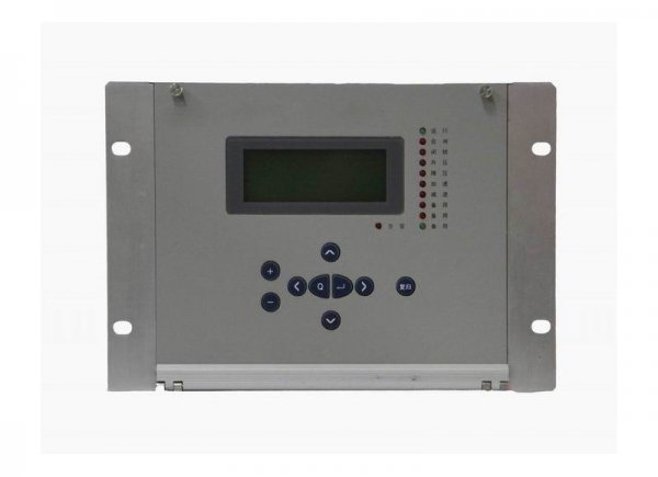
Automatic Quasi-synchronizing Device
Include 6 channels of Automatic Quasi-synchronizing Device,the main function is frequency modulation,voltage regulation and quasi-synchronizing judgement.
Product Description:
Product model: BEPR-511U Automatic Quasi-synchronizing Device
Product Feature and Benefits:
- Man-machine interface friendly, operation.
- The precision of the selected measuring modules can reach to the class 0.5.
- Configured with plenty of switch quantity input, convenient external tele-siginal access
- Equipped with high precision clock chip, and equipped with GPS hardware clock synchronization circuits , is advantageous for the whole system clock synchronization
- Equipped with high speed Ethernet communication interface, and integrate the IEC 60870-5-103 standard communication protocols
Product Configuration and Functions:
- One device can control up to 6 generators or 6 lines for paralleling-in.
- After settings and control words have been set up, only paralleling points are needed to be selected for each time of connecting into network.
- Multiple closing exits form the final closing exit via “And” logic relation.
- CB closing time angle difference is less than 0.5°.
- Three paralleling modes are supported, that is, difference frequency paralleling, common frequency paralleling, and no-voltage paralleling.
- Actuating can be done through digital input actuation
- Having the function of automatic angle turning, therefore, angle turning transformer is not required. Turning angles can be selected among 30 º leading,0 º, and 30 º lagging.
- The leading time is measured by using the CB auxiliary contact input signals.
- For the type of device which is used for generator units, automatic frequency regulating and automatic voltage regulating can be performed, and therefore, closing time is shortened.
- The automatic frequency and voltage regulating functions for each paralleling point can be enabled or disabled by using the control word.
- When common frequency occurs during the generator paralleling-in process, the device can automatically give out acceleration control commands.
- During the paralleling process, if the voltage becomes greater or less than the setting, the device will automatically block the voltage regulating function, and at the same time, closing will be blocked.
- During the paralleling process, if the frequency becomes greater or less than the setting, the device will automatically block the frequency regulating function, and at the same time, closing will be blocked.
- Having the functions of frequency difference (ΔF) blocking and voltage difference (ΔU) blocking closing.
- Chinese language or English language LCD display, easy for monitoring, setting and modifying.
- AC rated voltage: 100V or 57.74V(optional)
Technical Spefications:
Rated parameters
Rated D.C. voltage : 220V or 110V ( as required )
Rated A. C. dat:
a) Phase voltage 100 / V
b) Line extraction voltage 100 or 100 / V
c) Rated frequency 50 Hz
Power consumption :
a) D.C circuit normal : not larger than 25W
operation: not larger than 40W
b) A.C voltage circuit not larger than 0.5VA for each phas
Status voltage :
Input voltage to CPU and signal interface 24V (18V~ 30V )
The GPS clock pulse input level 24V (18V~ 30V )
Output status (optic coupled output ) permissive voltage 24V ( 18V ~ 30V )
driving power 150 mA
Main technical performance
Operating range for sampling circuits (5% tolerance )
Voltage: 0.4V~120V
Contact capacity
current capacity of the signal circuit contact 400VA
arc-breaking capacity of the signal circuit contact 60VA
Tripping and closing current
CB tripping current 0.5A~4A ( as required )
CB closing current 0.5A~4A ( as required )
Precision of elements
voltage element less than ± 5%
Inspection synchronization angle less than ± 1°
Timing element less than ± 20 ms
Frequency deviation less than ± 0.02 Hz
Slip difference value less than ±5%
Precision of measuring circuits for analog variables monitoring device equipped with the special measurement sub-module :
voltage : class 0.2
Insulation property
Insulation resistance
Insulating resistance between active parts and passive parts or casings and electrically unrelated circuits is measured by the 500V megaohmmeter to be not less than 50MΩ for the various circuits at different levels under the normal test atmospheric conditions.
Strength of insulating media
Under the normal test atmospheric conditions, the protection can withstand the power frequency withstand voltage test of 50 Hz, 2000V and 1 min without any breakdown flashover and element damages. During the test, as a voltage is applied at any tested circuit, the other circuits are inter connected and grounded with an equivalent potential.
Impact voltage
Under the normal test atmospheric conditions, the short-duration impact voltage test of 1.2 /50 µs standard lightning wave is done on the power input circuits. AC input circuits, output contact circuit to the ground and between circuits. The open test voltage is 5 kV.
Heat and moisture-proof performance
The protection can withstand the heat and moisture-proof test stipulated in GB/T 2423.9. The alternating heat and moisture-proof test is to be done at the highest temperature +40℃±2℃, the maximum humidity(93±3)%, for 48 hrs and at a cycle of 24 hrs. In 2 hrs before the test is finished, according to the requirements in section 2.3.1, the insulation resistance between the conducting circuits and external passive metals and casings and electrically unrelated parts are measured to be not less than 1.5 MΩ, the withstand voltage strength of the media not less than 75% of the voltage magnitude of the media strength test stipulated in the section 2.3.2.
Anti-electromagnetic interference
Electrostatic discharge
By GB/T 17626.2 1998 standard electrostatic discharge anti-interference level 4 test.
Radio frequency electromagnetic field radiation anti-interference
By GB/T 17626.3 1998 standard Radio frequency electromagnetic field radiation anti-interference level 3 test.
Electrical fast transient pulse group anti-interference
By GB/T 17626.4 1998 standard Electrical fast transient pulse group anti-interference level 4 test.
Surge immunity (impact)
By GB/T 17626.5 1998 standard Surge immunity (impact) anti-interference level 3 test.
Rf induction conduction disturbance degrees
By GB/T 17626.6 1998 standard Rf induction conduction disturbance degrees anti-interference level 3 test.
Power frequency magnetic field anti-interference
By GB/T 17626.8 1998 standard ower frequency magnetic field anti-interference level 5 test.
The pulse magnetic field anti-interference
By GB/T 17626.9 1998 standard The pulse magnetic field anti-interference level 5 test.
Damping oscillating magnetic field anti-interference
By GB/T 17626.10 1998 standard Damping oscillating magnetic field level 5 test.
Oscillation wave anti-interference
By GB/T 17626.12 1998 standard Oscillation wave anti-interference level 4 test.
Radiation emission limit test
By GB 9254-1998 standard Radiated emission limits A class test.
Mechanical performance
Vibration
The protection can withstand the impact duration test of the severity class I stipulated in the section 16.2 of GB/T 7261.
Impact
The protection can withstand the impact duration test of the severity class I stipulated in the section 17.4 of GB/T 7261.
Crash
The protection can withstand the impact duration test of the severity class I stipulated in the Chapter 18 of GB/T 7261.
Environment conditions
a) Ambient temperature :
operation : -20ºC~ +55ºC .
storage : -25ºC ~ +70ºC , no exciting variables are applied at the limit value and no irreversible changes
occur. The protection will operate normally after the recovery of temperature.
b) Relative humidity : maximum monthly average humidity 90 % at the lowest temperature of 25ºC, (no
condensation ). At the highest temperature of +40ºC, maximum humidity must not be
over 50 %.
c) Atmospheric pressure : 86 ~ 106 kPa ( relative altitude above sea level is less than 2 km ).
Application
BEPR-511U Digital Automatic Quasi-synchronizing Device(Hereafter to be simply called ‘the device’) is used for generator units incorporating into power networks ,and for substation busbars incorporating into transmission lines. The device features as fast speed, stable operating, high accuracy and high reliability. The device also has alarm functions, that is, during the connecting process, for the over-voltage, the under voltage, over frequency and under frequency on the system side, alarms can be sent out, and for the over voltage, under voltage, over frequency and under frequency on the side to be connected into the system, alarms can also be given.