Standby Power Automatic Switching Device(For all voltage levels)
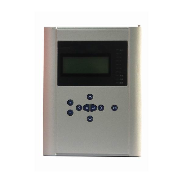
BEPR-851U digital standby power automatic switching device. The realization of automatic throw-over function adopts the graphic logically programmable mode, which would flexibly realize each automatic throw-over scheme, applicable for the control of the automatic throw-over device at various voltage levels.
Features and Benefits
- All English character LCD display, and clear and easy man-machine interface.
- The precision of the selected measuring modules (including KWH metering ) can reach to the class 0.5.
- To provide access to the accumulated pulse-degree side.
- High speed Ethernet interface is provided to integrated the IEC 870-5-103 standard communication protocol.
- High precision clock chips are used. The GPS time checking circuit is provided to realize the clock synchronism of the whole system.
- High speed Ethernet interface is provided to integrated the IEC 870-5-103 standard communication protocol.
- The core of CPU, the protection functional module is the powerful 32-bit micro- processors with large capacity RAM and Flash Memory. They are powerful to process data, perform logic calculation and store information. 8 to 50 recorded reports and 1000 events can be recorded. These information will not be lost even in power interruption.
Complete functional configuration
This product is internally integrated with many kinds schemes, such as automatic throw-over devices for substation or bridge switches, line switches, and transformers, etc. The user is only required to select the connection mode, and set the simple rated values settings, to reach the scheduled requirements. Special automatic throw-over schemes can be realized fast and reliably. Current and voltage protection can be loaded.
- Telemeter: I Ia,Ib,Ic,Ua,Ub,Uc,P,Q,f and other analog telemetry
- Telecontrol: Division and the normal remote control circuit breaker
- Telesignal:16way telesignalling open into the volume of the collection, installation of remote signal deformation, events, letters and other remote
- Remote pulse: 2-way electric-degree pulse input
- Out: Device has a 13 way out, of which 10 road trip because of the export-driven relay, 3-way signal drive for the notice of police.
- GPS time-checking
Technical Parameters
Rated parameters
Rated DC voltage: 220V or 110V (please specify in order),
permissive error: -20%~+10%.
Rated AC data:
a) Voltage 100V
b) Current 5A or 1A
c) Frequency 50Hz
Power consumption
a) DC power circuit Under normal work: no more than 25W
During operation: no more than 40W
b) AC voltage circuit No more than 0.5VA for each phase
c) AC current circuit when the rated current is 5A: no more than 1VA for each phase.
State vector level
The input state vector level of CPU and communication interface module
24V(18 V~30V)
GPS time synchronization impulse input level
24V(18 V~30V)
CPU output state variable (photo-coupling output)
Permitted level 24V(18 V~30V)
Driving capability 150mA
Main technical performance
Sampling circuit precise working range (10% error)
Voltage:0.4 V~120V
Current:0.08In~20In
Contact capacity
Signal circuit contact load: 400VA
Signal circuit contact arc break: 60VA
Sub-section tripping current and closing current
CB tripping current 0.5A~4A(please specify in the order)
CB closing current 0.5A~4A(please specify in the order)
Precision of various of component
Current component: ≤±5%
Voltage component : ≤±5%
Time component: ≤±20ms
Operation time (include relay inherent time)
Inherent operation time of transient output: ≤50ms
Insulation capability
Insulation resistance
The insulation resistance values between the charged parts and in charged parts, racks as well as irrelevant electrical circuits are measured by 500V megger and under normaltest atmospheric conditions, the resistance values of the various circuit at all levels are not lower than 50MΩ .
Media intensity
Under normal test atmospheric conditions, the device can tolerate the frequency 50Hz, signal input terminal to ground voltage, 500V, other circuit to ground voltage 2000V, 1min power-frequency withstand voltage test, without breakdowns, flashovers and element damages. During the test, when the voltage is applied at any tested circuit, all the other circuits are interconnected and grounded equip otentially.
Impulse voltage
Under normal experiment atmospheric conditions, the power input circuit, AC input circuit, output contact point circuit to ground, and all the circuits are able to endure short-time standard lightning impulse voltage test of 1.2/50μs, with open-circuit test voltage of 5kV.
Humidity and heat resistance performance
This device can endure the constant humidity and heat test regulated in GB/T
7261-2000, chapter 20, with highest test temperature +40℃, hightest humidity 95%,and test time of 48h. Within two hours after the completion of test, according to the requirements in 2.3.1, among the outside uncharged parts of each conductive circuit, the casing and irrelevant electrical circuits, the insulation resistance is measured, and it is no less than 1.5MΩ. The medium voltage withstand intensity is not below the 75% of voltage amplitude in medium intensity test.
Electromagnetic compatibility (EMC) capability
Electrostatic discharge immunity test
This device can endure the electrostatic discharge immunity test Class IV stipulated in GB/T 17626.2-1998.
Radiated Radio-frequency electromagnetic field immunity test
This device can endure the radiated, radio-frequency, electromagnetic field immunity test Class III stipulated in GB/T 17626.3-1998.
Electrical fast transient/burst immunity
This device can endure the electrical fast transient/burst immunity test Class IV stipulated in GB/T 17626.4-1998.
Surge immunity test
This device can endure the surge immunity test Class III stipulated in GB/T 17626.5-1999.
Immunity to conducted disturbances, induced by radio-frequency fields
This device can endure the immunity to conducted disturbances, induced by radio-frequency fields test Class III stipulated in GB/T 17626.6-1998.
Power frequency magnetic field immunity test
This device can endure the power frequency magnetic field immunity test Class V stipulated in GB/T 17626.8-1998.
Pulse magnetic field immunity test
This device can endure the pulse magnetic field immunity test regulated Class V stipulated in GB/T 17626.9-1998.
Damped oscillatory magnetic field immunity test
This device can endure the damped oscillatory magnetic field immunity test Class V stipulated in GB/T 17626.10-1998.
Oscillatory waves immunity test
This device can endure the oscillatory waves immunity test Class IV stipulated in GB/T 17626.12-1998.
Radiated emission limited value test
This device has passed the radiated emission limited value test A stipulated in GB 9254-1998
Mechanical performance
Vibration
This device can endure the grimness vibration duration test of severity Class I stipulated in 16.3 of GB 7261-2000.
Impact
This device can endure the impact duration test of severity Class I stipulated in 17.5 of GB 7261-2000.
Collision
This device can endure the collision test of severity Class I stipulated in Chapter 18 of GB 7261-2000.
Environment conditions
a) Environment temperature:
Work: -20℃~+55℃(as required in the contact)
Storage: −25℃~+70℃, no energized variables are applied at the limit value and no irreversible changes occur. The device can normally operate when the temperature recovers.
b) Relative humidity: The wet month on the mean maximum relative humidity was 90%, At the same time of the month on average minimum temperature of 25 ℃ and the surface without any dew. The highest temperature of + 40 ℃, relative humidity of the mean maximum no more than 50%.
c) Atmospheric pressure: 86kPa~106kPa(lower than 2km at the altitude above sea level).